verifiedAIS-156 | UN38.3 | CE | IEC 62619 | 12-market export certification system
EN
TIANQIULi-ion Export
LAB BENCH #04 ACTIVE · AIS-156 Rev.3 / ISO 26262 ASIL-B motive-grade validation guideFIRMWARE: v4.82_CAN20BISO 11898 compliant matchingCAN 2.0B auto-adaptive

Commercial three-wheeler BMS selection andCAN bus communication protocol engineering guide

Under hard acceleration on a gradient, a commercial three-wheeler or heavy e-moped draws a transient inrush of 3–5× its rated current, while coasting downhill and regenerative braking inject a high back-EMF surge. This guide uses motive-grade laboratory data to show why a commercial BMS must have a sub-milliohm ≥120V withstand array, integrated pre-charge soft start and millisecond transient overload suppression.

cable
CAN baud rate250 / 500k
bolt
MOSFET array withstand≥ 120V
balance
Balancing accuracy≤ 15mV
flash_on
Short-circuit response< 20μs

verifiedRecorded on the vehicle bus: Vpp 2.12V · differential 2.01V stable · 500k CAN-H/L · BMS 4G IoT telemetry online

graphic_eqBUS CURRENT & VOLTAGE500k CAN-H/L
Bus waveform timing2.00μsCAN_H 3.5V
Differential voltage (DIFF)2.01V STABLEVpp 2.12V (recessive level 2.48V)
terminalVehicle frame 0x18F0E5F472.4V | 42.1A | 89%
verifiedCell delta 0x18F0E6F4Δ13mV PASS

Specification notice:Reference values only — batch and duty-cycle variation applies. Contact us for detailed specifications.

warningWhy Storage BMS Fails On-Vehicle

Why a household storage BMS blows its MOSFETs on a vehicle

warning

Three electrical shocks that define motive duty

Inrush under hard acceleration reaches 3–5× rated current, while coasting and regenerative braking inject a high back-EMF surge. An ordinary household storage BMS usually withstands only 80V with no cascaded surge path, so the MOSFETs are punctured instantly. A commercial motive BMS needs a low-resistance ≥120V array, integrated pre-charge soft start and millisecond transient overload suppression.

memory

Reference vehicle bus frame set

0x18F0E5F4 DLC 08 [72.4V | 42.1A | 89%], 100ms cycle; 0x18F0E6F4 DLC 08 [C_MAX 3.321V / C_MIN 3.308V], Δ13mV PASS; 0x18F0E7F4 DLC 08 [MOS_T 34℃ / BAT_T 31℃] HEAT NORM. Waveform Vpp 2.12V (recessive 2.48V), differential 2.01V stable, ACK FRAME OK.

scienceAutomotive Grade Validation

Industrial-grade motive BMS laboratory and bench validation

From hardware-level transient current tolerance to frame consistency and full-temperature impedance analysis, the whole chain is exercised against real unpaved-road duty.

monitor_heart

High-speed bus signal integrity and common-mode rejection

Chopper speed control on a commercial e-three-wheeler generates severe reverse-PWM interference from the motor. Using an isolated CAN transceiver with a common-mode choke, testing confirms no retransmission and no frame loss even with ±36V transient ground-potential shift.

Rise time 18.4ns · isolation withstand 2500Vrms · BER < 10⁻¹²
thermostat

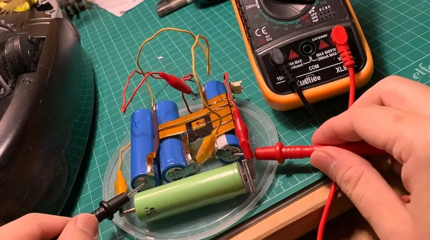
200A continuous load thermal rise and anti-arc cut-off

A double-sided array of 24 automotive low-resistance MOSFETs (1.1mΩ on-resistance per device) with 3mm gold-plated copper busbars removes local current hot spots, so heavy loaded climbs run continuously without nuisance thermal protection.

MOS rise ΔT 24.2℃ · 600A (3s) peak capability · IP67 potted
balance

Dynamic cell balancing and charge/discharge diagnostics

Instead of the 35mA passive heat-dissipating drain used by ordinary storage boards, an inductive bidirectional 2A energy-transfer balancer realigns 24 series cells to within 15mV in 45 minutes, even under high-rate fast charging in extreme overseas heat.

2.0A bidirectional balancing · > 92% transfer efficiency · +28% pack life
electric_bolt

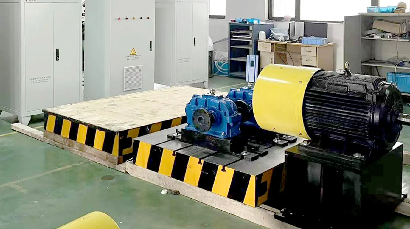
Dynamometer back-EMF spike and surge suppression test

When a 1.2-tonne loaded commercial vehicle brakes hard on a descent, the regenerative EMF from the PMSM slams back into the BMS terminals. A two-stage RC snubber plus a 5000W instant-breakdown TVS clamp protects the main chip.

BEMF peak 118V · TVS clamp response 1.2ps · 120V reverse withstand, 0% breakdown · 100,000 shock cycles
gavelTechnical Parameter Comparison

Commercial motive BMS vs household storage BMS: key parameters

Rigorous test engineering data. Never move a low-cost storage protection board onto a high-dynamic delivery e-motorcycle or a loaded cargo tricycle — the risk is a full-batch recall.

AIS-156 mandatory matching spec
Core design parameterTIANQIU commercial motive BMS (automotive grade)Ordinary storage BMS (household grade)On-vehicle failure consequence
MOSFET withstand margin≥ 120V (150V TVS bidirectional clamp)60V – 80V (no margin at the limit)Back-EMF from hard braking punctures the MOS instantly and the pack loses control
Over-current and transient peak tolerance200A continuous / 600A steady with 3s pulse50A continuous / 100A transient (no pulse margin)Repeated over-current trips on loaded hill starts, or the board catches fire
Hardware pre-charge circuitIntegrated PTC / high-power milliohm pre-charge (millisecond)No independent pre-charge path (direct connection)Controller bulk capacitance draws tens of amps of arc at power-up and carbonises the connector
Cell balancing mechanismActive bidirectional inductive transfer (1.5A – 2.0A)Passive resistive heat dissipation (30 – 50mA only)Voltage spread on large cells accumulates fast; real range drops more than 40% within six months
Communication interfaces and isolationDual-isolated CAN 2.0B + isolated RS485 + 4G telemetryUnisolated UART / short-range Bluetooth onlyMotor common-mode pulses enter the bus, blanking the cluster and locking the control chip
Independent charge/discharge thermal protection6–8 NTC channels (charge low-temp 0°C / discharge high-temp 65°C locked independently)1–2 total sensing channels (shared threshold)Winter lithium plating punctures the separator; summer charging swells the pack into thermal runaway

These parameters are consistent with those in the uphill cut-off troubleshooting guide and can be cross-checked against it.

Specification notice:The figures above are engineering reference values. They may differ with production batch, configuration and actual duty cycle, and the percentages for life, efficiency, availability and coverage are engineering estimates and bench references. Contact us for the detailed specification sheet.

cloud_syncTelematics & Instrument Cluster Sync

On-board cluster and 4G IoT telematics frame definitions

Native support for J1939 and standard CAN 2.0B extended frames, interoperating with mainstream platforms (Navixy, Traccar, Wialon) and digital LCD clusters across India, Indonesia, Southeast Asia and beyond.

CAN 2.0B extended frame · 29-bit identifier
Frame IDCycleByte fieldSignal definitionResolution / offset
0x18F0E5F4100 msBYTE 0~1Pack status broadcast: total voltage (V)0.1V/bit (0~100V)
0x18F0E5F4100 msBYTE 2~3Instantaneous current (A)0.1A (offset −300A)
0x18F0E5F4100 msBYTE 4SOC (%)1%/bit (0~100%)
0x18F0E5F4100 msBYTE 5SOH (%)1%/bit (state of health)
0x18F0E5F4100 msBYTE 6~7Main alarm code (ALARM)16-bit fault bit mask
0x18F0E6F4500 msBYTE 0~1Cell and temperature extremes: maximum cell voltage1mV/bit
0x18F0E6F4500 msBYTE 2Index of the maximum cellCell 1~24
0x18F0E6F4500 msBYTE 3~4Minimum cell voltage1mV/bit
0x18F0E6F4500 msBYTE 5Highest temperature point1°C (offset −40°C)
0x18F0E6F4500 msBYTE 6MOSFET temperature1°C rise

Supports an instrument power-on self-test comms acknowledgement with reverse-polarity check and CRC-8 redundancy. A DBC database file is provided so vehicle ECUs and VCUs can load it straight into Vector CANoe for communication simulation. Host tools and protocol files are in the BMS host software and protocol open centre.

Specification notice:The figures above are engineering reference values. They may differ with production batch, configuration and actual duty cycle, and the percentages for life, efficiency, availability and coverage are engineering estimates and bench references. Contact us for the detailed specification sheet.

router4G IoT Diagnostics Ecosystem

Live 4G IoT remote diagnostics for overseas fleets

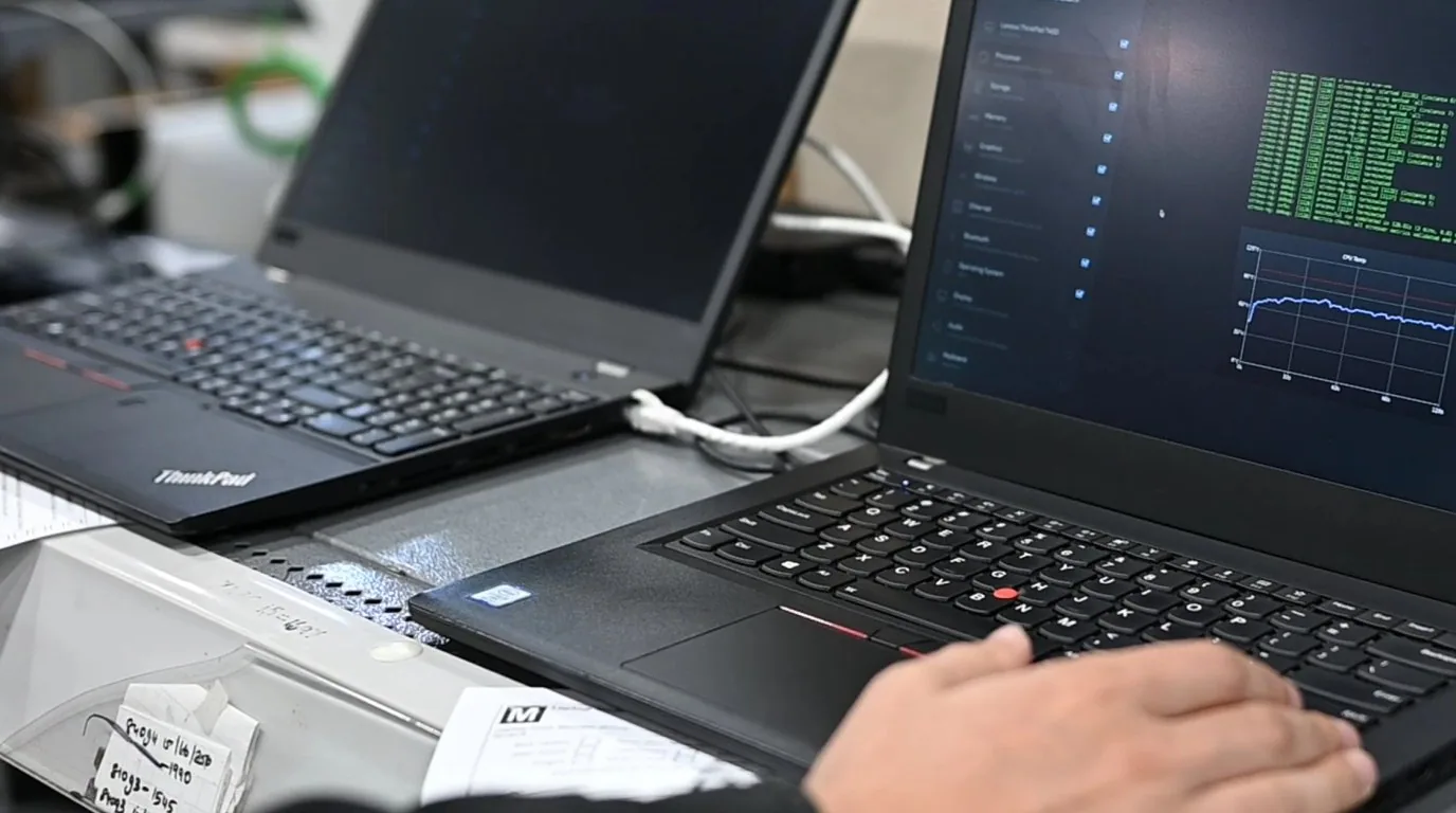
For cross-border three-wheeler fleets and swap operators, the BMS provides a direct 4G CAT-1 module interface supporting MQTT / HTTP / TCP reporting and seamless OTA firmware updates.

Battery diagnostic analyser showing balancing and SOC curves

Plug and play on mainstream platforms

Navixy · Traccar · Wialon

Built-in Navixy, Traccar and Wialon parsing scripts put GPS position and battery voltage / SOC on one screen with no secondary development.

Engineer issuing remote commands over a BMS CAN bus link

Remote immobilisation and capacity calibration (OTA)

MQTT / HTTP / TCP

On overdue rental or physical tampering the system issues a soft immobilisation command; it also self-learns and corrects cell internal resistance after export, with seamless OTA firmware updates.

Test bench for 48V, 60V and 72V instrument comms

Instrument-maker protocol library pre-adapted

One-wire · CAN · 485, auto-adaptive

Compatible with the mainstream cluster protocols supplied by EVE, Jinpeng and Zongshen, auto-adapting across one-wire, CAN and 485 to cut vehicle integration work.

helpEngineering Trouble Shooting

The six most common BMS selection and commissioning faults overseas

A practical software and hardware troubleshooting guide compiled from OEM customers in seven overseas markets, from line assembly to after-sales field verification.

01. On a loaded climb, why does the cluster suddenly go blank and the pack report an “instantaneous over-current disconnect”?expand_more
Usually because the short-circuit and transient protection delays in the BMS are set too tight and the discharge MOSFET has insufficient continuous over-current margin. A loaded three-wheeler pulls 300A–450A for 1–2 seconds at start-up. A storage-grade BMS often misreads 200A sustained beyond 50ms as a short circuit and locks out. The TIANQIU motive BMS has three-tier over-current tolerance: 200A continuous with no time limit, 350A overload buffered for 10 seconds, and short-circuit protection above 600A cutting in within 20μs — matching the motor start transient precisely.
02. There is a violent arc when the controller connects to the battery plug, sometimes burning the pins. How do we eliminate it?expand_more
The motor controller contains thousands of microfarads of high-voltage bulk capacitance. Without a pre-charge circuit, that capacitance looks like a dead short at power-up, and the inrush can exceed 500A in an instant, striking an arc. The TIANQIU automotive BMS includes an independent pre-charge control path: a 100Ω/10W power resistor charges the controller capacitance under smooth current limiting, and only once the bus voltage reaches 95% of pack voltage does the main MOS close with zero differential — eliminating the arc and fire risk.
03. On the assembly line the oscilloscope shows nothing but error frames on the CAN bus. How do we diagnose it?expand_more
Work through three checks: ① termination resistance — with the system powered down, measure between CAN_H and CAN_L and confirm one 120Ω terminator at each end of the bus for an equivalent 60Ω (missing terminators or too many nodes cause severe ringing); ② baud-rate conflict — confirm whether cluster and BMS have agreed 250kbps or 500kbps, with crystal deviation within ±1.5%; ③ transceiver common-mode ground shift — check that battery negative (B−) and vehicle ground are connected, and where tens of volts of floating common-mode voltage exist, use a dedicated isolated CAN module with an isolation transformer.
04. Why does passive balancing cause local high-temperature alarms and repeated pack failures in hot, humid Southeast Asia?expand_more
Passive balancing burns the energy of the highest cell as pure heat through SMD power resistors (P = I²R). Inside a sealed IP67 enclosure with a wide spread across 24 cells, multiple balancing resistors heat continuously, local temperature can exceed 75°C, and cells near the BMS board age faster under sustained thermal stress. Commercial motive designs must move to active inductive energy-transfer balancing, with efficiency above 90% and almost no waste heat, greatly reducing thermal-runaway risk inside the enclosure.
05. What does India AIS-156 Amendment III actually mandate for the BMS?expand_more
For L-category (light two- and three-wheeler) EVs, AIS-156 Amendment III requires: ① thermal event warning — an audible and visual alarm on the cluster at least 5 minutes before a detected cell thermal runaway; ② high-precision sampling and a data black box — the BMS must retain extreme temperatures and over-current logs from at least the last 100 charge/discharge cycles, protected against power-loss data loss; ③ dual hardware-level cut-off — beyond the software MOS shut-off, an independent second-level hardware trip or fuse mechanism.
06. When a customer uses a third-party GPS tracker, how do SOC and alarm codes reach the cloud accurately?expand_more
The TIANQIU BMS provides independent physical RS485 (Modbus-RTU) and CAN (J1939) channels as standard. A vehicle GPS tracker such as Teltonika or Queclink connects its RS485 A/B input to the matching BMS pins, and the customer enters our Modbus register address map in the tracker host software (for example 0x0010 for total voltage, 0x0012 for SOC, 0x001A for error codes) — data then parses and uploads to the cloud with no code development. The full register manual is in the BMS host software and protocol open centre.
file_downloadEngineering Toolkit

Request the motive BMS protocol whitepaper and engineering samples

Get the complete Vector CANoe .DBC protocol file, the Modbus-RTU register addressing manual and AIS-156 certification drawings, and apply for one commissioning-free engineering sample for dynamometer benchmarking.

  • Vector CANoe standard .DBC matrix file
  • 16S–24S LFP / NCM motive BMS datasheets and schematics
  • Engineering sample dispatched by SF Express / DHL within 48 hours
  • One-to-one online commissioning with a senior hardware / CAN engineer
mailEngineering desk: sales@erickshawtrikebattery.com
callTechnical hotline / WhatsApp: +86 13922702227
location_onEBattery Office, Room 310I, Huilange BLDG, No. 273, Huangpu Blvd W, Tianhe District, Guangzhou 510620, Guangdong, China
scheduleEngineering team makes contact within 24 hours on working days to confirm series count and baud ratememoryFree cluster harness definition and protocol parsing supportlocal_shippingEngineering sample shipped within 48 hours for dynamometer benchmarking

Specification notice:The figures above are engineering reference values. They may differ with production batch, configuration and actual duty cycle, and the percentages for life, efficiency, availability and coverage are engineering estimates and bench references. Contact us for the detailed specification sheet.

lockProtected by NDA

The vehicle protocols, controller brands and model data you submit are commercial secrets. They stay strictly confidential, and a mutual NDA can be signed first.