verifiedAIS-156 | UN38.3 | CE | IEC 62619 | 12-market export certification system
EN
TIANQIULi-ion Export
TIANQIU B2B POWERTRAIN FAILURE DOSSIER · DOC-REF: FA-2026-UPHILL192.4A inrush on a 14° gradientSized for China and India gradient duty

Diagnosing a loaded three-wheeler that cuts out uphill,and the BMS current-limit principle behind it

Most owners assume the battery has failed. In reality this is a storage-grade BMS protection threshold mismatch. On the flyover ramps of Lagos, the heavy-freight routes of Pune and the rolling hills around Nairobi, large numbers of converted three-wheelers (Keke / Tuk-Tuk) fitted with non-standard or storage-type packs black out mid-gradient. This is not only a lost shift — a loaded tricycle can roll backwards. This report publishes the full root-cause model, captured on vehicle dynamometers and digital oscilloscopes.

warning
High-incidence gradient14°~18°
scale
Laden mass1,250 kg
bolt
Transient inrush current192.4 A
battery_alert
Typical storage BMS limit80~100 A
trending_down
Bus voltage sag64.2V ➔ 49.1V
timer
MOSFET shut-off time18 ms

verified100ms sampling window · sized for China and India gradient duty

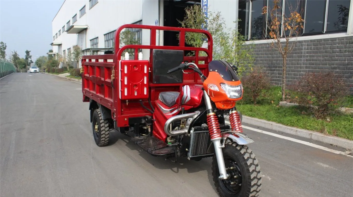
Heavy-duty cargo tricycle hauling bricks and cement bags uphill
trending_upInrush current · over-current trip192.4 A
show_chartField Evidence

On-vehicle gradient waveform analysis, in numbers

When a loaded tricycle pulls away on a brick-yard or builders-merchant ramp, motor back-EMF collapses to zero and the armature enters a locked or half-locked rotor condition. The measurement proves that storage-grade BMS boards use a very conservative continuous-current time constant (typically 100ms): the moment a heavy start arrives, the controller applies full duty-cycle PWM and blows straight through that threshold.

scale1,250 kgLaden massLoaded pull-away on brick-yard ramps
bolt192.4 ATransient inrush uphillContinuous cut-off threshold 100A · trip point 12ms
battery_alert80~100 ATypical storage board limitSingle-stage 100A / 100ms fuse curve
timer18 msMOSFET shut-off timeBus collapsing 64.2V ➔ 49.1V

Specification notice:The figures above are engineering reference values. They may differ with production batch, configuration and actual duty cycle, and the percentages for life, efficiency, availability and coverage are engineering estimates and bench references. Contact us for the detailed specification sheet.

troubleshootRoot-Cause Autopsy

Three cut-off root causes, compared against scope traces

Most overseas dealers blame capacity and simply order more amp-hours. In fact 92% of cut-offs come from the three electrochemical and BMS control mismatches below.

electric_bolt

Instant overcurrent trip

At low speed under full load, motor back-EMF collapses towards zero and the phase windings conduct heavily. The motor momentarily demands 3–4x its rated locked-rotor pulse (150A~220A).
Storage board: single-stage, 100A / 100ms fuse.
TIANQIU standard: two-stage motive curve, 300A (1s) / 450A (100ms).

Fault E-01 · Symptom: a violent jolt, dash goes dark, self-recovers 5s after the throttle is released
device_thermostat

Thermal throttling intervention

Low-rate, high-resistance cells (such as salvaged storage cells above 1.8mΩ internal resistance) driven hard on a long climb heat the module core past 65°C within four minutes through Joule heating (Q=I²Rt).
Thermal probe reading: 72°C localised at the MOSFET bank and tabs.
BMS response: NTC sensing forces a lockout and refuses restart until cooled.

Fault E-02 · Symptom: dies mid-climb, needs 15 minutes parked to cool before it will start
battery_alert

Cell sag trip and false low-voltage lockout

A textbook weakest-link effect. The pack meter may still show 50% remaining, but if one ageing cell in a 24S string is behind, its terminal voltage instantly breaches the 2.5V cut-off floor under high current.
Cell delta dynamics: 15mV at rest ➔ 380mV at full load.
Protection logic: hard cell under-voltage trip.

Fault E-03 · Symptom: cuts out uphill with three bars left, and charge level rebounds as soon as the charger is connected
Smart BMS management board under cell thermal testing
precision_manufacturingHardware Countermeasures

Precision internal-resistance grading and dynamic balancing

A cell-level dynamic-sag analyser shows exactly how string 14 collapses non-linearly at 150A.

A-grade 3C high-rate cellsCell resistance < 0.5mΩ12~16 automotive NMOS300A / 3s surge capability
  • 100% four-wire internal-resistance grading: cell-to-cell resistance spread held at ≤0.15mΩ, eliminating the false early-sag trips that end a climb.
  • Solid thermally-conductive aluminium busbars and an automotive-grade shunt architecture: no flying wire solder joints. A 5oz copper-control board and an external high-rate copper shunt hold mainboard temperature rise to 52°C even on a 45°C tropical climb.
  • High/low-temperature infrared inspection: double-layer thick-copper busbars and the MOSFET array are scanned for even heat distribution inside a 55°C environmental chamber, with no local hot spots.
balance≤0.15mΩCell resistance spread
thermostat≤52℃Mainboard temperature rise
wb_sunny45℃Tropical climb ambient
fact_check100%Four-wire grading coverage
fact_checkSafety reminders before you start
  • Never short BMS P- to B- to keep a vehicle running — that removes the cell-level second line of protection and can start a fire.
  • Always ballast the vehicle to rated payload when reproducing a climb; an empty tricycle cannot reproduce the inrush stall.
  • Keep a solid earth reference — brushless motor PWM common-mode noise can destroy a multimeter ADC front end.
calculateEngineering Calculation Matrix

Controller peak current vs BMS protection threshold matrix

Why does a 1500W motor still cut out on a 100A lithium pack? Because the controller current ceiling and the inverter efficiency factor were both ignored. This is the on-vehicle calibration matrix behind the mandatory sizing formula.

Recommended duty class: TIANQIU industrial motive pack
Motor specificationBus nominal voltageController current limit (A)Loaded uphill transient peakWrong selection (market storage pack)TIANQIU industrial motive standardRecommended cable (AWG)
1000W differential motor48V DC35A ± 1.5A75A ~ 95A50A board (instant cut)80A continuous / 150A transient (5s)8 AWG pure copper
1500W heavy passenger (Keke)60V DC45A ± 2A110A ~ 140A80A board (thermal trip)120A continuous / 240A transient (3s)6 AWG silicone
2200W cargo climber60V / 72V60A ± 2A150A ~ 185A100A generic board (punch-through)160A continuous / 350A transient (3s)4 AWG high-temp silicone
3000W two-speed polar motor72V DC80A ± 3A200A ~ 240A150A board (frequent UV lockout)200A continuous / 450A transient (5s)2 AWG / 35mm²

The selection envelope must cover continuous current and the transient crest. The pull-away surge and the second shock of crossing a speed hump fall inside the same time-constant window; sizing a board on continuous current alone is the single biggest cause of gradient cut-offs. For board and vehicle matching detail see the commercial BMS selection and CAN bus guide.

Specification notice:The figures above are engineering reference values. They may differ with production batch, configuration and actual duty cycle, and the percentages for life, efficiency, availability and coverage are engineering estimates and bench references. Contact us for the detailed specification sheet.

functionsMandatory Sizing Formula

BMS rated and transient trip threshold formula

I_bms_peak ≥ (P_motor / (V_cutoff × η)) × K_uphill, where η (motor efficiency) ≈ 0.82 and K_uphill (gradient load factor) = 2.2~2.8.

lightbulb

The overseas procurement rule that prevents burn-back

The BMS rated discharge current (continuous) must be at least 1.5x the controller maximum rated current; the transient trip current must reach 3.0x or more, and the transient delay threshold must be calibrated to 2000ms~3000ms so that speed humps and gradient pull-away torque crests are enveloped rather than tripped.

warning

Cold and altitude duty widen the mismatch

Below 10°C cell DC resistance multiplies and the sag slope (ΔV = I × R_internal) steepens, so under-voltage protection trips earlier. The compensation strategy for high-latitude and highland packs is covered in the sub-zero charge/discharge and PTC self-heating guide.

report

Never "test" the cause by shorting P- to B-

Shorting bypasses all semiconductor protection. With the cell-level second line removed, an external short circuit leads directly to fire. Diagnose through the four-step SOP below instead.

engineeringStandard Operating Procedure

Overseas workshop: four-step on-site diagnostic SOP

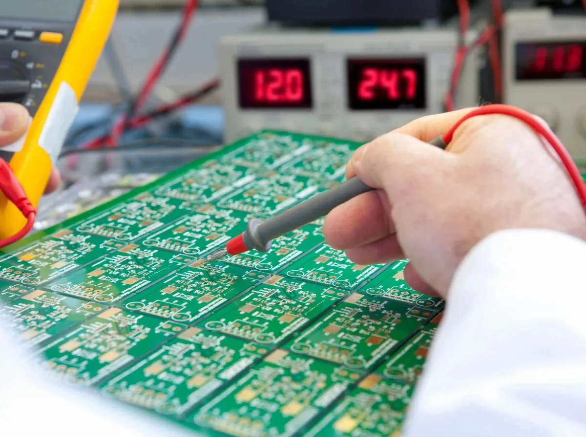
When a rider reports "it stops every time I go up a slope", the technician must not open the pack first. Bring a standard multimeter, a clamp meter and an infrared thermometer, and close the diagnosis loop through these four steps.

  1. 01multimeter

    Step 1 — Dynamic sag test at the output connector

    Put the probes across the battery output busbars, prop up the rear wheel and hold the brake (or sit on a measured 10° gradient), then apply full throttle for 2 seconds:
    Verdict A | sag < 4.5V and still cuts out: the cells are healthy and the BMS transient current threshold is simply set too low. No pack replacement needed — re-parameterise or fit a motive board.
    Verdict B | sag > 12V collapse: cell resistance is extreme or a string is open. The module is deeply polarised or the cells are gassing; open the pack and repair at cell level.

    Tools: digital multimeter / clamp meter
  2. 02bluetooth

    Step 2 — Read the BMS protection freeze frame over Bluetooth / UART

    Open the TIANQIU mobile engineering app and read the first freeze frame recorded at the moment of cut-off: ERR-02: Peak-OCP (hardware overcurrent) · ERR-05: Cell-UVP (cell under-voltage) · ERR-09: MOS-OTP (MOSFET over-temperature). Frame definitions and register mapping are in the BMS selection and CAN bus guide.

    Tools: smartphone app / USB-TTL host software
  3. 03thermometer

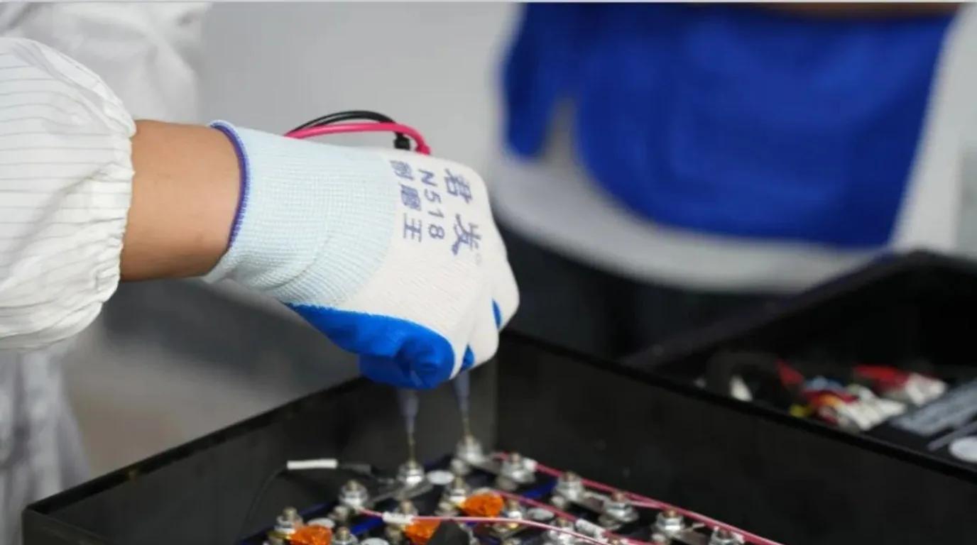
    Step 3 — Infrared scan of terminals, posts and Anderson plugs

    After 100 metres of loaded climbing, lift the seat base immediately and inspect the Anderson connectors for oxidation, looseness or cold-soldered cable lugs. Alarm threshold: above 60°C at a terminal, a poor joint of only 15mΩ will eat 1.5V and dissipate 150W at 100A, dropping the voltage at the controller input below its own cut-off.

    Tools: thermal imaging camera / contact thermocouple
  4. 04settings_input_component

    Step 4 — Check motor phase demagnetisation and Hall sensor slip

    If pack sag and BMS current thresholds are both within specification but the vehicle still cuts out, move to the motor. Heat-induced demagnetisation lowers the torque constant, so the controller raises its current limit to hold torque — which closes a self-reinforcing overload loop.

    Tools: scope with Hall signal breakout / resistance bridge
Quality engineer running a warranty inspection with digital tools
ruleInstant Diagnosis Decision Table

Instant diagnosis: three symptoms, three actions

Lagos and Delhi service points keep this bench setup on hand: read the symptom, locate the failure layer, and stop opening packs at random.

  • Symptom: restarts immediately after cut-off ➔ BMS instant overcurrent protection (replace with a motive board).
  • Symptom: needs the charger plugged in before it powers up ➔ BMS hard under-voltage lockout (repair the weak cell).
  • Symptom: cut-off with a burnt smell and soft insulation ➔ oxidised / cold-soldered terminals, or main cable gauge far too small.
speed
Verdict A sag < 4.5VBMS threshold too low
warning
Verdict B sag > 12VExtreme cell resistance
device_thermostat
Terminal alarm threshold> 60℃
cable
Poor joint at 15mΩEats 1.5V / 150W
helpTroubleshooting FAQ

Three-wheeler powertrain faults: seven field questions answered

The seven questions our after-sales teams in Africa, South Asia and Latin America are asked most often at the service counter.

Q1: The lead-acid pack never cut out uphill — why does a lithium pack of the same amp-hour rating cut out immediately?expand_more
This is a classic misunderstanding. Lead-acid is a rigid electrochemical battery with no internal semiconductor protection board: at 150A of uphill demand it simply sags hard on its own internal resistance (perhaps 60V down to 42V), and the motor slows and softens but never switches off. A lithium pack must be protected by BMS MOSFETs, and if the pack uses a low-cost storage-type BMS the overcurrent gate is clamped at 80A~100A. Cross that line and the MOSFETs cut the circuit within 15 milliseconds to prevent combustion — which is exactly the "sudden blackout" the rider feels. The fix is a professional three-wheeler BMS with a 3C motive discharge delay curve.
Q2: Does mixing a lead-acid charger into a lithium pack make uphill cut-offs worse?expand_more
It is absolutely forbidden. Lead-acid chargers include a de-sulphation high-voltage pulse stage and a float stage, and their termination voltage (a 60V lead-acid bank floated above 72V) is wholly incompatible with LiFePO4. Sustained use drives the lithium BMS into over-voltage protection or gasses the cells, accelerating divergence. Once cell delta is stretched beyond 300mV, the weakest cell hits the 2.5V floor first under load and hard-cuts the whole string. Charger matching rules are in the charger matching and fast-charge safety guide.
Q3: Why do uphill cut-offs become more frequent in winter or at altitude, such as the Kenyan highlands or the Andes?expand_more
Below 10°C, lithium-ion migration resistance inside the LiFePO4 lattice rises sharply and electrolyte viscosity increases, so cell DC resistance multiplies. Under heavy uphill load the internal-resistance drop (ΔV = I × R_internal) makes the cell voltage fall on a much steeper slope and low-temperature under-voltage protection trips easily. TIANQIU cold-region and high-altitude models ship with a micro-power cell heating film and embed a dynamic temperature-derating curve in the BMS algorithm.
Q4: Can an overseas distributor raise the overcurrent threshold through the Bluetooth app or host software?expand_more
On a TIANQIU industrial motive board, our engineers can issue a remote authorisation key and the delay parameter can be adjusted within the calibrated safety margin through the host tool (for example widening a 150A delay from 1000ms to 2500ms). On a generic market storage board it is absolutely forbidden. Those boards carry very few MOSFET channels (usually only four to six) on thin steel busbars, so raising the software value makes the MOSFETs absorb enormous avalanche energy at the trip instant — the board will catch fire or burst.
Q5: How does poor cable gauge or the wrong Anderson connector produce a phantom cut-off?expand_more
Many conversion shops use 10 AWG or thin copper-clad aluminium cable on a 60V 1500W powertrain to save cost. At 120A of climbing current the cable itself becomes a resistive heater, and the voltage drop across it can reach 3V~5V. That pushes the voltage at the controller input below its own low-voltage disconnect (LVD) and melts connector housings. Standard recommendation: above 1500W use 6 AWG or 4 AWG tinned multi-strand high-temperature silicone cable with genuine Anderson SB120 / SB175 flame-retardant connectors.
Q6: What exactly is the fault where the vehicle only wakes up after the charger is connected?expand_more
This is BMS hard under-voltage lockout protection, the highest safety tier. When the BMS sees a cell fall below the absolute limit under load (for example LiFePO4 below 2.0V), the MCU decides the cell may be at risk of internal lithium plating and a short circuit, so it forces the discharge path open and refuses to self-reset. Only when a charger is connected and external current injection is detected does the BMS confirm a safe charging environment and release the lockout. The weak cell must be located with a delta analyser and replaced or balanced.
Q7: How does TIANQIU eliminate uphill tripping at the hardware level?expand_more
TIANQIU applies a full-chain heavy-duty three-layer defence: ① new-energy A-grade 3C high-rate LiFePO4 cells with very low internal resistance (< 0.5mΩ) that do not collapse under high current; ② an in-house EV-grade smart BMS with 12~16 automotive low-resistance NMOS devices and a standard 300A 3-second surge capability; ③ thick one-piece stamped and laser-welded copper busbars instead of wiring, eliminating local thermal resistance. Every pack completes a continuous locked-rotor test on a full-load dynamic gradient bench before it leaves the plant.
file_downloadEngineering Diagnostic Toolkit

Get the uphill cut-off diagnosis tree and an engineering test pack

Send your target motor specification, controller current limit and destination market, and the TIANQIU powertrain institute will reply within 24 hours on working days with a full dynamometer matching study and a custom sample-pack proposal.

  • 24-page fault waveform reference set
  • BMS hexadecimal register error lookup table
  • Cable gauge and voltage-drop selection calculator (Excel)
  • Targeted sampling and powertrain matching tests for overseas OEMs and large fleets
mailEngineering desk: sales@erickshawtrikebattery.com
callTechnical / WhatsApp: +86 13922702227 (English, French and Arabic spoken)
location_onShipped point-to-point from our Shenzhen and Dongguan engineering centres
scheduleMotor and controller parameters confirmed within 24 hours on working daysengineeringBMS host software and parameter tool provided free of chargeinventory_2Motive test pack dispatched within 48 hours

Specification notice:The figures above are engineering reference values. They may differ with production batch, configuration and actual duty cycle, and the percentages for life, efficiency, availability and coverage are engineering estimates and bench references. Contact us for the detailed specification sheet.

lockProtected by NDA

Vehicle drawings, controller brands and duty-cycle data you submit stay strictly confidential. A mutual NDA can be signed first.