
Clamp meter · peak current
Measure the true peak current at loaded pull-away and on a gradient, then confirm the BMS transient delay window of 3–5× continuous current.
First-hand evidence against OCP mis-diagnosisBuilt for overseas conversion workshops, fleet maintenance crews and after-sales engineers who are stuck when a vehicle “dies on a gradient, will not fully charge, loses range in a cliff-edge drop, throws a comms fault on the dash, or trips mid-charge”. This centre carries the complete field logic tree, the BMS alarm-code quick reference and hands-on hardware procedure, so a frontline technician can close the case in 15 minutes.
verifiedField Diagnostics Manual 2026.V4 · bilingual · every threshold quoted from the production automotive-grade BMS firmware
Specification notice:Reference values only — batch and duty-cycle variation applies. Contact us for detailed specifications.
Field fault-finding is not guesswork: it is a repeatable, measurable procedure. Start with coverage and localisation time, then look at how faults actually distribute.
Specification notice:The figures above are engineering reference values. They may differ with production batch, configuration and actual duty cycle, and the percentages for life, efficiency, availability and coverage are engineering estimates and bench references. Contact us for the detailed specification sheet.
With resident workshop tooling, oscilloscope-level checks and the dedicated BMS host-software capture tool, diagnosis happens at the workshop floor.
Measure cell-to-cell voltage delta (ΔV) string by string with high-precision instruments to locate weak cells and loose busbar bolts before condemning a whole pack.
Connect the portable host software straight to the BMS and capture live frames, including millisecond-grade records of OCP, UVP and over-temperature events.
Track the charge/discharge knee points and internal-resistance temperature slope to separate lithium plating or a micro-short from genuine capacity fade, and decide whether balancing is still worthwhile.
Verify the charger output curve against the BMS closed-loop protocol, and eliminate the permanent BMS lockout caused by legacy lead-acid chargers, reverse polarity or a floating earth.
Built from commercial three-wheeler and heavy-duty e-moped duty cycles: root cause, the BMS protection that fires, and the field procedure to follow.
| Symptom | Probable root cause | Automotive BMS protection | Field checks and handling | In-depth guide |
|---|---|---|---|---|
| 1. Instant cut-out under a heavy load or hard acceleration on a gradient (vehicle shuts down) Urgency: high · road safety | Transient current exceeds the BMS protection limit; motor stall or controller DC-link capacitor inrush at power-up; a workshop fitted an energy-storage-grade low-power BMS. | Discharge over-current protection (OCP) Transient response ≤ 2ms, preventing busbar short and MOSFET breakdown | Clamp-meter the peak current at loaded pull-away; Confirm the BMS enables a 3–5× continuous-current transient delay; If an ESS-grade board is fitted, replace it with a commercial high-rate BMS immediately. | Peak over-current selection manual |
| 2. Charger shows a red alarm on plug-in, or the pack nuisance-trips after 5–10 minutes Frequency: very high · charging blocked | One string far too low or too high, tripping cell over-voltage (OVP); charger-to-BMS handshake timeout; charging-port NTC sensor wire cold-soldered or loose. | Cell over-voltage protection (OVP) Charging MOS loop opens at 3.65V per string, preventing swelling | Read the highest cell voltage at the trip instant on the host software; If the delta exceeds 100mV, run high-precision passive/active balancing; Measure CAN_H/L wiring resistance at the charge head to rule out packet loss. | Charger handshake protocol spec |
| 3. Dash reads 100% then collapses to 20% and cuts out after 3–5 km Classic case · phantom SOC dive | Actual usable capacity has collapsed (mislabelled second-life cells); one string shows abnormally high DC internal resistance, so the transient drop under load hits the under-voltage line. | Cell under-voltage protection (UVP) Any string at ≤ 2.50V trips the system, protecting the cells from scrap | Run a simulated heavy-load discharge with the vehicle braked on a stand; Watch per-string live voltage curves on the host software and find the string that falls off a cliff; Measure the weak cell IR — above 2× the factory baseline it must be replaced. | Cell drop and IR standards |
| 4. Dash shows no SOC percentage, or reports a CAN communication fault code Signal bus · protocol dropout | Dash and BMS baud rate mismatch (250kbps vs 500kbps); no 120Ω termination resistor at either bus end; CAN_H and CAN_L reversed or poorly seated. | Bus communication watchdog (WDT) Comms loss beyond 3s triggers restricted limp mode or a dash fault lamp | With power off, measure resistance across CAN_H and CAN_L — it should read 60Ω; Use an oscilloscope probe to check dominant/recessive differential levels (2.5V ± 1.0V); Re-flash the dash-specific communication protocol firmware from the host software. | CAN topology troubleshooting chart |
| 5. Power halves or the dash flags a speed limit at midday in tropical heat High ambient · thermal protection | Ambient above 45℃ in North Africa and the Middle East with a sealed, unvented battery bay; loose terminal bolts generating heat; the BMS probe sees cell temperature above 55℃ and derates against thermal runaway. | Active thermal derating (OTP) 50% current limit above 55℃, discharge cut-off above 65℃ | Scan the interior with a thermal imaging camera for abnormal hot spots; Check whether the bay has a reflective heat shield and forced-convection ducting; Confirm NTC sensors are firmly bonded and their resistance has not drifted. | Tropical heat dissipation retrofit guide |
| 6. Pack will not power on or charge after standing for 2+ weeks (0V at the output) Long idle · deep over-discharge | The immobiliser or GPS unit was left on constant live, drawing milliamps; excessive BMS quiescent drain; cell voltage fell below 2.0V and the safety lockout engaged, so the charger cannot start. | Sleep lockout and 0V anti-explosion protection Prevents blind high-current charging of a deeply over-discharged pack that may have lithium plating | Open the enclosure and measure the absolute voltage of every string; If all strings read above 2.2V, wake them with a 0.05C trickle repair charger; If any string has fallen below the 1.5V copper-foil dissolution limit, never recharge it — it must be scrapped and replaced. | Long-term storage drain rules |
Urgency and frequency labels come from our overseas ticket statistics. Every protection threshold is the BMS firmware default and can be tuned to a specific duty cycle.
Specification notice:The figures above are engineering reference values. They may differ with production batch, configuration and actual duty cycle, and the percentages for life, efficiency, availability and coverage are engineering estimates and bench references. Contact us for the detailed specification sheet.
Never open a pack and start swapping cells without baseline data. Follow the three-step loop and you will know within 15 minutes whether the fault lies in the vehicle harness, the BMS protection or the cells themselves.
Non-destructive checks before any internal BMS protection is released:
· Inspect the high-current Anderson connectors for arcing, oxidation, burning or poor seating.
· Multimeter the static open-circuit output voltage to confirm whether the pack is locked out.
· Megger the insulation resistance from terminals to the metal enclosure (> 50MΩ required).
Read the BMS digital record and let the data find the fault:
· Connect a laptop through a USB-CAN box and export the historical alarm log and fault-code snapshot.
· Sweep all 16 or 24 cell voltages: is the static delta above the 30mV warning line?
· Validate every BMS NTC channel against ambient temperature to rule out a shorted or open sensor.
Prove it under load and pin down the fault boundary:
· Connect a programmable DC electronic load or run the vehicle loaded uphill, logging the instant voltage-drop slope.
· Connect the standard fast charger and watch the 0–10A ramp for handshake behaviour and relay closing.
· Issue the diagnostic report: BMS parameter reset, passive balancing repair, or return-to-factory hardware repair.
Laboratory-grade diagnosis, brought to the workshop floor. Together these instruments and read-out limits form the minimum kit for a resident overseas technician — and all of it can ship with your container order.
Measure the true peak current at loaded pull-away and on a gradient, then confirm the BMS transient delay window of 3–5× continuous current.
First-hand evidence against OCP mis-diagnosisExport live frames, historical alarm logs and fault-code snapshots directly from the BMS, with J1939 and custom protocol export support.
Reads 16/24 cell voltages without opening the packCheck dominant/recessive CAN_H and CAN_L levels (2.5V ± 1.0V); with power off, node-to-node resistance should read 60Ω.
Locates baud-rate and termination faultsWatch the 0–10A ramp for handshake and relay closure, and verify CC/CV curve matching against overcharge.
Stops legacy lead-acid charger lockoutScan the battery bay for abnormal hot spots and trace loose terminal bolts or poorly seated busbars.
Essential above 45℃ ambientInsulation resistance must exceed 50MΩ; a programmable DC load logs the instant voltage-drop slope to pin the fault boundary.
Static plus dynamic verificationOnce the field diagnosis has narrowed the fault, use the matching topic for selection review, protocol alignment or a warranty claim:
How an ESS-grade low-power BMS left behind by a conversion workshop shuts a vehicle down mid-climb, and how to set the transient delay and hysteresis window.
Open the selection and limiting guidearrow_forward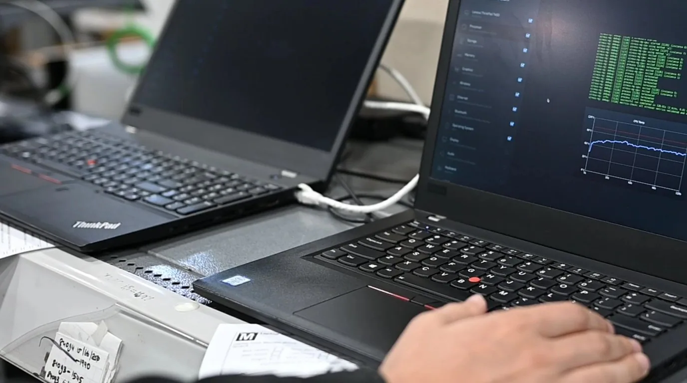
Work through pin resistance, differential levels and dash-specific firmware re-flash to clear protocol dropout and missing SOC.
Open the CAN bus guidearrow_forward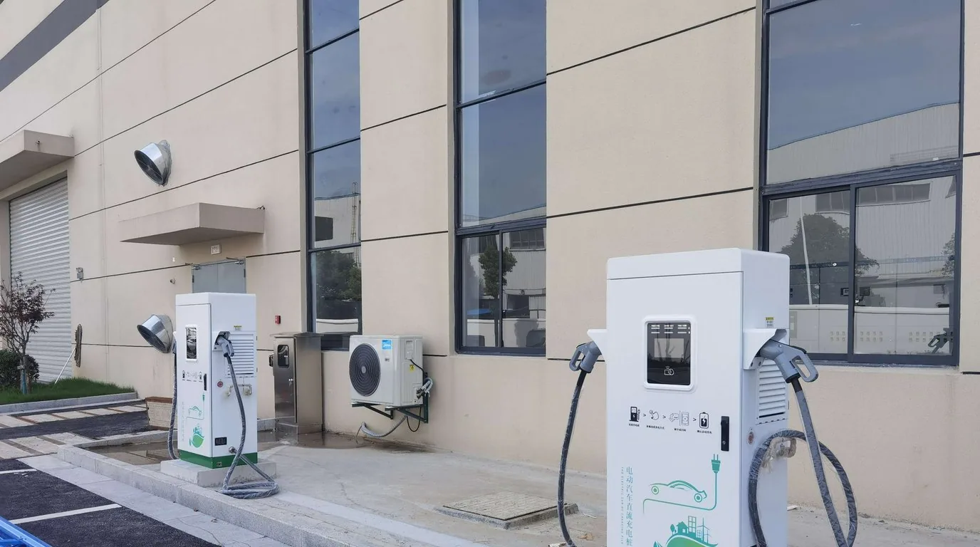
Sizing wide-range chargers, wiring the charging-port NTC sensor, and preventing BMS lockout from a floating earth.
Open the charger guidearrow_forward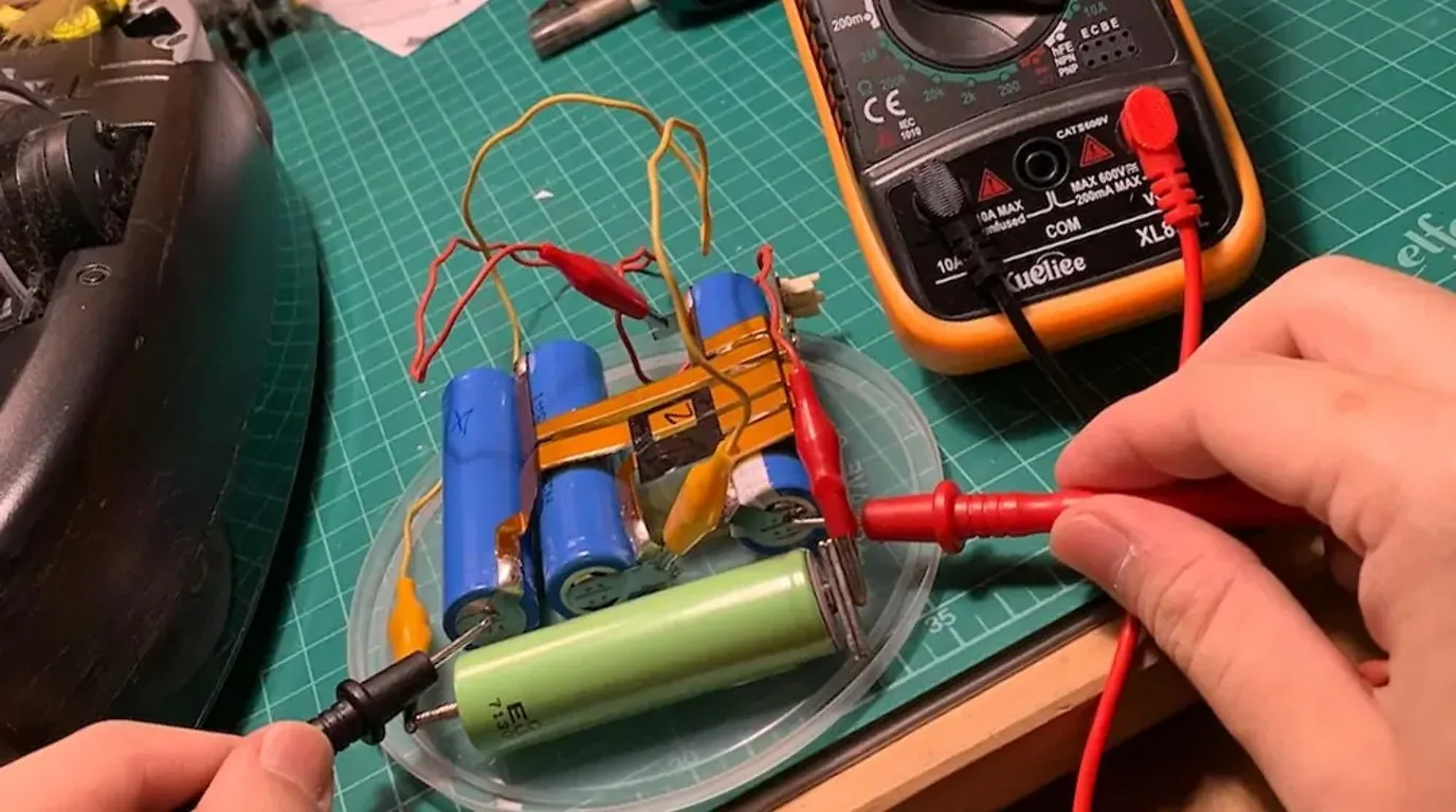
The 3,500 deep-cycle fade baseline, how to read IR spread, and when balancing still helps versus when a module must be replaced.
Read the cycle-life whitepaperarrow_forwardThe local replacement route, decision thresholds and freight responsibility once a defect is confirmed by 4G IoT or host-software logs.
See warranty and claimsarrow_forwardLong ocean transit and slow local parts rotation shape how these questions get asked, so the answers below are written for the workshop floor.
Give us the full fault characteristics and published data. Our senior powertrain specialists review the ticket and assign a named engineer within 24 hours on working days.
Specification notice:The figures above are engineering reference values. They may differ with production batch, configuration and actual duty cycle, and the percentages for life, efficiency, availability and coverage are engineering estimates and bench references. Contact us for the detailed specification sheet.
Diagnostic logs, vehicle wiring photos and commercial details are used only for liability assessment and technical review, and are never disclosed to third parties.