
Why a loaded cargo tricycle loses power uphill:it is not the capacity, it is the current limit
The conclusion first: a loaded tricycle that feels weak on a climb is almost never short of capacity. A gradient needs more tractive force, tractive force comes from torque, and torque is bought with bus current — and when that current exceeds the controller limit or the BMS protection threshold there are only two outcomes: limited speed (soft) or cut-out (hard). The site’s field capture is blunt: a loaded tricycle at a 1,250 kg laden mass pulling away on a 14° ramp drew a 192.4A transient inrush, collapsed the bus from 64.2V to 49.1V and shut the MOSFETs off in 18ms — while a conventional storage-grade BMS limits at just 80–100A. This page gives the estimation method, the controller and cable matching basis, and a four-step diagnostic checklist.
verifiedEvery test figure on this page is given as a range with its conditions, never as a point guarantee for one vehicle · no amounts are published, and the signed quotation governs
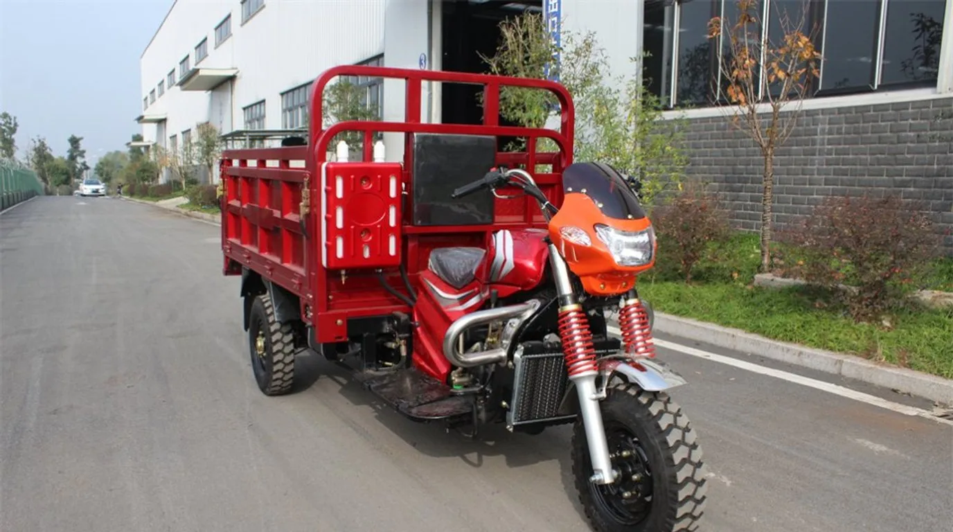
Controller limit, loaded climbing peak and cable gauge (AWG) matrix
Why does a 1500W motor still cut out on a 100A pack? Because the controller current ceiling, the inverter efficiency factor and the transient crest were all ignored. The table puts motor specification, bus voltage, controller limit, loaded climbing peak and recommended cable together so the selection can be read off directly.
| Motor specification | Bus nominal voltage | Controller current limit (A) | Loaded uphill transient peak | Wrong selection (market storage pack) | Industrial motive standard | Recommended cable (AWG) |
|---|---|---|---|---|---|---|
| 1000W differential motor | 48V DC | 35A ± 1.5A | 75A ~ 95A | 50A board (instant cut) | 80A continuous / 150A transient (5s) | 8 AWG pure copper |
| 1500W heavy passenger (Keke) | 60V DC | 45A ± 2A | 110A ~ 140A | 80A board (thermal trip) | 120A continuous / 240A transient (3s) | 6 AWG silicone |
| 2200W cargo climber | 60V / 72V | 60A ± 2A | 150A ~ 185A | 100A generic board (punch-through) | 160A continuous / 350A transient (3s) | 4 AWG high-temp silicone |
| 3000W two-speed polar motor | 72V DC | 80A ± 3A | 200A ~ 240A | 150A board (frequent UV lockout) | 200A continuous / 450A transient (5s) | 2 AWG / 35mm² |
These are bench and vehicle calibration figures used for selection comparison, not a precise guarantee for an individual vehicle. The pull-away surge and the second shock of crossing a speed hump fall inside the same time-constant window, so sizing a board on continuous current alone is the single biggest cause of gradient cut-offs; the full matching and diagnostic route is in the uphill cut-off and BMS current limit guide. An undersized cable produces a phantom cut-off too: the cable itself becomes a resistive heater and its voltage drop can pull the controller input below its own low-voltage disconnect.
Specification notice:The figures above are engineering reference values. They may differ with production batch, configuration and actual duty cycle, and the percentages for life, efficiency, availability and coverage are engineering estimates and bench references. Contact us for the detailed specification sheet.
How to estimate the current a climb needs: mass × gradient → force → current
No dynamometer is required: given the total vehicle mass, the gradient and the steady climbing speed, the required tractive force converts into bus current. The result is an estimate to be used as a range — good enough to choose a BMS class and a cable gauge, not a point guarantee for one vehicle.
- 01scale
Step 1 — work out the tractive force
F ≈ m × g × (sin θ + Cr × cos θ), where m is total vehicle mass (kerb weight plus payload, kg), g ≈ 9.81, θ is the gradient angle and Cr the rolling resistance coefficient (about 0.015 on paved surfaces, rising to 0.035 on loose or broken ground). Take 1,250 kg laden on a 14° ramp with Cr = 0.02 on unpaved ground: the gradient component is about 2,968 N and rolling about 238 N, giving roughly 3.2 kN of tractive force.
Cr: 0.015 paved · 0.02–0.035 unpaved (published basis) - 02speed
Step 2 — convert to wheel power
P_wheel = F × v. At a steady climbing speed of 10 km/h (about 2.78 m/s): P_wheel ≈ 3,206 N × 2.78 m/s ≈ 8.9 kW. Note that this is the continuous power to hold a steady climb — the pull-away transient is a separate and larger event, covered in step 4.
A slower climb needs less current but lasts longer, so temperature rise gets worse - 03bolt
Step 3 — convert to bus current
I ≈ P_wheel ÷ (V_bus × η_c), with η_c the combined motor and controller efficiency, taken as 0.80–0.85 in engineering practice. At 0.82 the bus power is about 10.9 kW, and at a 64V bus that is roughly 170A. That sits in the same bracket as the 192.4A climbing inrush recorded on the site, and inside the platform’s 150–250A continuous rating.
Varies with payload, gradient, speed and the efficiency assumed; treat the result as a range - 04shield
Step 4 — pick the protection class on the transient multiple
Pull-away and a stalled start are far above a steady climb, so verify against I_bms_peak ≥ (P_motor ÷ (V_cutoff × η)) × K_uphill, with η ≈ 0.82 and K_uphill (gradient load factor) at 2.2–2.8. The practical rule: the BMS continuous rating must be at least 1.5x the controller maximum rated current, the transient trip current at least 3.0x, and the transient delay calibrated to 2000–3000ms so speed humps and gradient pull-away torque crests are enveloped rather than tripped.
I_bms_peak ≥ (P_motor ÷ (V_cutoff × η)) × K_uphill
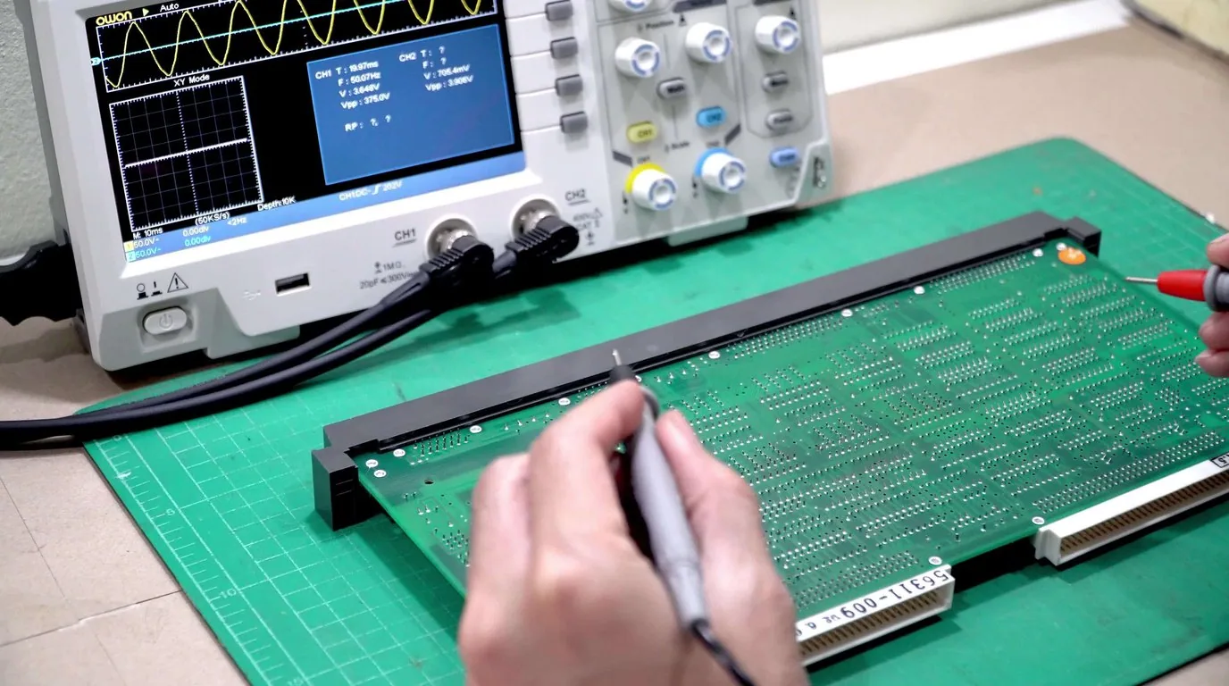
Why heavy load demands motive-grade cells: P = I²R, spelled out
Climbing current does not pass the battery by — it flows through it continuously. Resistive heating follows P = I²R: double the current and the heat becomes four times greater. Stationary energy-storage (ESS) cells are built for 0.2C operation in a temperature-controlled room: high internal resistance and weak heat paths. Fitted to a loaded three-wheeler, the inrush and climbing currents cause a cliff-edge voltage collapse that latches the protection board, followed by obvious fade within months. That is the root reason a heavy-load vehicle fades faster than a light one in the same year, and why an enclosed tropical battery bay must be given cooling room.
- A 6.0x discharge-rate gap: motive cells sustain 3.0C continuous and 5.0C transient pulse for 15 seconds; ESS cells polarise violently above 0.8C and their protection board latches off.
- Internal resistance and Joule heating: cell DC internal resistance is ≤0.35 mΩ on motive cells against ≥1.20–1.80 mΩ on ESS cells. At 3.4× the resistance, the same current produces 11.5× the Joule heat and accelerates separator breakdown.
- Voltage sag under a step load: at a 150A step, a motive cell sags about 0.12V and climbs the gradient smoothly, while an ESS cell sags about 0.58V, collapses and locks out.
- How cycle life is tested: motive cells are tested at 1.0C full charge and discharge to ≥3,500 cycles at ≥80% SOH; ESS cells under vehicle current fall short of 600 cycles (about nine months), their multi-thousand-cycle claims having been tested at 0.2C light cycling only.
- Run a dynamic sag test: load the output connector for 2 seconds. Sag under 4.5V and still cutting out means the cells are healthy and the BMS transient threshold is too low; sag above 12V means extreme cell resistance or an open string, and the pack needs cell-level repair.
- Read the BMS freeze frame: use the host tool or app to identify the first recorded fault and separate hardware over-current (Peak-OCP), cell under-voltage (Cell-UVP) and MOSFET over-temperature (MOS-OTP) — the three have different remedies.
- Infrared-scan terminals and Anderson plugs: check immediately after 100 metres of loaded climbing. Above 60℃ at a terminal is the alarm threshold, because a joint of only 15mΩ eats 1.5V and dissipates 150W at 100A.
- Check motor phase windings and Hall sensors: if pack sag and BMS thresholds are both in specification and the vehicle still cuts out, move to the motor. Heat-induced demagnetisation lowers the torque constant, forcing the controller to raise its current limit into a self-reinforcing overload loop.
Loaded climbing power and cut-out questions
The lead-acid pack never cut out uphill — why does a lithium pack of the same amp-hour rating cut out?expand_more
How much current does a loaded climb actually need, and how do I estimate it?expand_more
Can I just raise the BMS over-current threshold to stop the cut-out?expand_more
How do I choose the cable gauge and Anderson connector — can thin cable cause a phantom cut-off?expand_more
The vehicle slows first and then cuts out on a climb — is that the controller or the battery?expand_more
Get a firm configuration and quote against your payload and gradient
Send destination port, rated payload, typical gradient and daily distance, motor rating and controller current limit and we will model the matching capacity band, BMS continuous and transient classes, cable gauge and connector specification, with FOB / CIF pricing and lead time per band.
- Selection advice and pricing within 24 hours on working days
- Every test figure carries its conditions and range — never a point guarantee
- Pilot packs available for a loaded climbing bench re-check before committing to a container
Specification notice:The figures above are engineering reference values. They may differ with production batch, configuration and actual duty cycle, and the percentages for life, efficiency, availability and coverage are engineering estimates and bench references. Contact us for the detailed specification sheet.
Vehicle drawings, controller brands and duty-cycle data you submit stay strictly confidential. A mutual NDA can be signed first.