
Smart BMS battery packs:buying a battery is buying its BMS
Fit a different BMS to the same batch of A-grade motive cells and the vehicle behaves differently. Set one protection threshold conservatively and a loaded climb cuts power; leave a passive balancing board generating heat and the voltage spread accumulates until range falls off a cliff within six months. The BMS is not an accessory to the cells — it is the pack brain and its insurance. This page covers the five things that actually decide the outcome: matching protection thresholds to the duty cycle, the service-life difference between active and passive balancing, how to read CAN 2.0B frames and Modbus-RTU registers, the DBC file and host tooling, and OTA plus DTC remote service.
verifiedEvery threshold, frame ID and register address on this page comes from the published engineering pages on this site (commercial BMS and CAN bus guide, BMS host software and protocol centre, uphill cut-off diagnosis) and can be cross-checked against them.
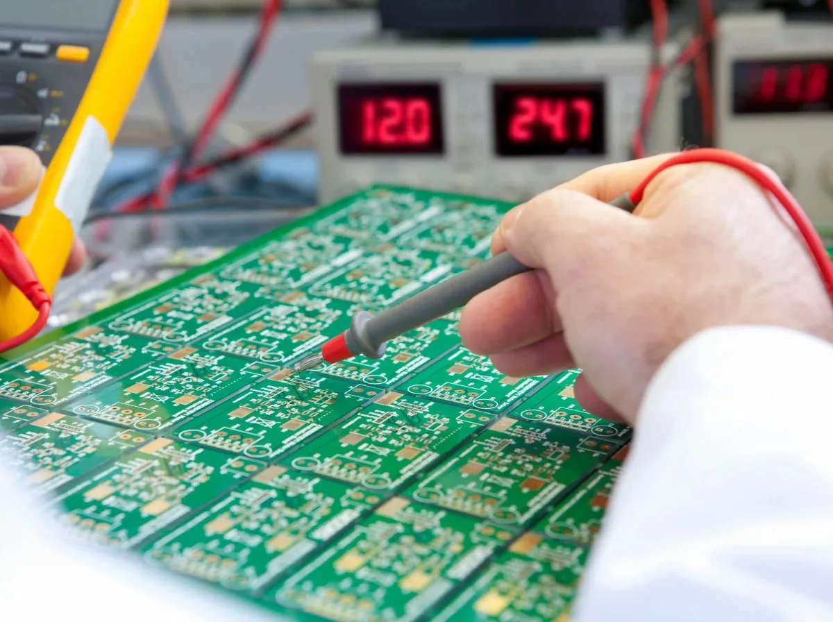
The four hard numbers on a motive-grade BMS
Specification notice:The figures above are engineering reference values. They may differ with production batch, configuration and actual duty cycle, and the percentages for life, efficiency, availability and coverage are engineering estimates and bench references. Contact us for the detailed specification sheet.
Protection thresholds: storage BMS against motive-grade BMS
Put the thresholds in one table and it becomes clear that a cut-off is not a cell failure but a protection curve that does not match the duty cycle. The consequence column comes from on-vehicle and bench records.
| Core parameter | Storage BMS (typical failure point) | Motive-grade BMS | What the mismatch does on the vehicle |
|---|---|---|---|
| MOSFET withstand margin | 60V – 80V (no margin at the limit) | ≥ 120V (150V TVS bidirectional clamp) | Back-EMF from hard braking punctures the MOS and the pack loses control |
| Over-current and transient tolerance | 50A continuous / 100A transient (no pulse margin) | 200A continuous / 600A with 3s pulse | Repeated over-current trips on loaded hill starts |
| Over-current delay | Single-stage 100A / 100ms | 200A continuous unlimited / 350A buffered 10s / > 600A cut in 20μs | A 300–450A start transient lasting 1–2 seconds is misread as a short circuit and locks out |
| Hardware pre-charge path | None (direct connection) | PTC / high-power milliohm pre-charge (millisecond) | Controller bulk capacitance arcs at power-up and carbonises the connector |
| Cell balancing | Passive resistive drain 30 – 50mA | Active bidirectional inductive 1.5 – 2.0A | Spread accumulates fast; real range falls more than 40% within six months |
| Charge/discharge thermal protection | 1 – 2 total sensing channels (shared threshold) | 6 – 8 NTC channels (charge low-temp 0°C / discharge high-temp 65°C locked independently) | Winter lithium plating punctures the separator; summer charging swells the pack |
The table follows the laboratory bench basis already published on this site and shares its source with uphill cut-off and BMS current-limit diagnosis; it can be compared item by item with the commercial BMS and CAN bus guide.
Specification notice:The figures above are engineering reference values. They may differ with production batch, configuration and actual duty cycle, and the percentages for life, efficiency, availability and coverage are engineering estimates and bench references. Contact us for the detailed specification sheet.
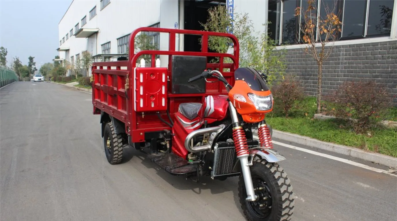
Why a loaded climb triggers "protection": the real threshold mismatch
Owners usually assume the battery has failed. In most cases a protection threshold does not match the duty cycle. On-vehicle: on a 14°–18° continuous gradient at 1,250 kg laden mass, the transient inrush reaches 192.4A, the bus sags from 64.2V to 49.1V, and the MOSFETs shut off within 18ms. This section sets out the three trigger paths, each of which needs a different response.
- Instant over-current trip: at low speed under full load the motor back-EMF collapses towards zero and the controller applies full duty cycle, so the transient demand reaches 3–4× the rating (150–220A). A storage board with a single-stage 100A / 100ms curve misreads that as a short circuit and locks out. The symptom is a violent jolt, a dark dashboard and self-recovery about 5 seconds after the throttle is released.
- Thermal throttling: low-rate, high-resistance cells under sustained climbing heat the module core past 65°C within four minutes, the NTC forces a lockout and the pack refuses to restart until cooled. The symptom is dying mid-climb and needing about 15 minutes parked.
- Cell sag and false under-voltage: a single lagging cell in a 24S string breaches the 2.5V floor under high current, with the spread stretching from Δ15mV at rest to Δ380mV at full load. The symptom is a cut-off uphill with three bars left, and charge that rebounds as soon as the charger is connected.
- Sizing rule: the BMS rated discharge current must be at least 1.5× the controller maximum rated current; the transient trip must reach 3.0× or more, and the transient delay must be calibrated to 2000–3000ms so gradient pull-away and speed-hump torque crests are enveloped rather than tripped. Cold widens the mismatch further: below 10°C cell DC resistance multiplies and the sag slope steepens.
- Dynamic sag test: full throttle for 2 seconds across the output busbars — sag below 4.5V with a cut-off means the threshold is too low; sag above 12V means extreme cell resistance or an open string
- Read the BMS freeze frame: ERR-02 Peak-OCP (hardware over-current) / ERR-05 Cell-UVP (cell under-voltage) / ERR-09 MOS-OTP (MOSFET over-temperature)
- Infrared scan of terminals and connectors: above 60°C at a terminal, a joint of only 15mΩ eats 1.5V and dissipates 150W at 100A
- Check cable gauge and motor condition: above 1500W use 6 AWG or 4 AWG silicone cable, and rule out phase demagnetisation and Hall sensor slip that close a self-reinforcing overload loop
Active and passive balancing: the difference shows up in service life
Passive balancing (resistive drain)
Burns the highest cell down as heat- cancelBalancing current30 – 50mADissipated through SMD power resistors, P = I²R
- cancelHeat inside the enclosureInside a sealed IP67 pack, several resistors heating at once can push local temperature past 75°C
- cancelEffect on service lifeCells nearest the BMS board sit under sustained thermal stress and age faster
- cancelBalancing speedWith a wide spread across 24 cells, levelling takes hours
- cancelWhere it fitsSmall capacity, few series cells, cost-first light duty
Active balancing (bidirectional inductive transfer)
Moves energy into the lowest cell- check_circleBalancing current1.5 – 2.0A bidirectionalInductive energy transfer above 92% efficiency
- check_circleHeat inside the enclosureEssentially no waste heatGreatly reduces thermal-runaway risk inside the pack
- check_circleEffect on service lifeAbout +28% pack lifeSpread is continuously levelled, removing the weakest-link effect where one cell hits the floor while healthy cells still hold charge
- check_circleBalancing speedWithin 15mV in 45 minutesHolds on a 24S pack even after high-rate fast charging in extreme heat
- check_circleWhere it fitsHigh-string motive packs, hot and humid markets, fleet assets that must last
CAN 2.0B frames and Modbus-RTU registers at a glance
Both "can I watch the battery on my phone" and "how do I read a 48V BMS" are answered here: some data travels on CAN 2.0B extended frames, some over isolated RS485 Modbus-RTU registers, and the two physical channels are independent.
| Interface / frame | Address or byte field | Signal definition and resolution |
|---|---|---|
| CAN 2.0B extended frame | 29-bit identifier | ISO 11898-2 compliant; loads directly into a Vector CANoe .DBC database for communication simulation |
| 0x18F0E5F4 · 100ms | BYTE 0~1 / BYTE 2~3 | Pack status broadcast: total voltage 0.1V/bit; instantaneous current 0.1A (offset −300A) |
| 0x18F0E5F4 · 100ms | BYTE 4 / BYTE 5 | SOC 1%/bit; SOH 1%/bit |
| 0x18F0E5F4 · 100ms | BYTE 6~7 | Main alarm code: 16-bit fault bit mask |
| 0x18F0E6F4 · 500ms | BYTE 0~1 / BYTE 2 / BYTE 3~4 | Maximum cell voltage 1mV/bit; index of that cell (1~24); minimum cell voltage 1mV/bit |
| 0x18F0E6F4 · 500ms | BYTE 5 / BYTE 6 | Highest temperature point 1°C (offset −40°C); MOSFET temperature 1°C |
| RS485 / Modbus-RTU | 0x0010 / 0x0012 / 0x001A | Read total voltage / read SOC / read error codes (function codes 0x03 / 0x06 / 0x10, with a CRC16 checksum library) |
| CAN physical layer | 250k / 500k bps · load < 21.8% | Hardware jumper or software adaptive; one-click auto-scan from the host; CRC-8 / J1850 checking |
When the DBC file is loaded into Vector CANoe, set Baudrate to 250kbps and Sample Point to 80%, and leave "force standard 11-bit frame" unticked, so Pack_Voltage, Cell_Max_V and Discharge_Limit display correctly. The register manual, C / Python examples and the third-party GPS tracker integration route are in the BMS host software and protocol centre; cluster integration is covered by the commercial BMS and CAN bus guide.
Specification notice:The figures above are engineering reference values. They may differ with production batch, configuration and actual duty cycle, and the percentages for life, efficiency, availability and coverage are engineering estimates and bench references. Contact us for the detailed specification sheet.
Three steps from commissioning to parameter download and remote service
A standard industrial configuration flow: physical connection, parameter burn-in, then OTA and DTC service after export — all on one link.
- 01cable
Physical hardware connection
Use the isolated USB-to-CAN / 485 adapter box on the pack aviation comms plug or debug port, with the shield reliably grounded. The adapter provides 1500VDC self-recovering opto-isolation, so motor start-stop interference does not reach the low-voltage debug side.
1500VDC self-recovering opto-isolation - 02monitor_heart
Host handshake and status capture
Open the host software and click auto-scan baud rate. It identifies the battery hardware version and cell count automatically, reads every cell voltage, temperature and alarm record, then exports the fault history codes (DTC logs) and full-cycle CSV data so spread, resistance and temperature trends can be assessed.
Auto-matches the 250k / 500k protocol templates - 03verified_user
Calibrate, burn in and service remotely
Download the continuous and peak over-current thresholds and the regenerative cut-off for the target market road conditions (Kenyan hot gradients, Philippine heavy loads), then burn them into EEPROM with one click after dual-check confirmation. After export, the 4G Cat.1 module (MQTT / HTTP / TCP) supports seamless OTA firmware updates, remote immobilisation and self-learning cell-resistance calibration. With no laptop on site, the built-in BLE 5.0 module lets a phone app scan the enclosure QR code to view cell spread, export CSV logs and adjust protection delays within safe permissions.
Dual-check write protection · on-site rollback
BMS battery questions we get every week
What is a BMS, and why does buying a battery mean buying a BMS?expand_more
Why does the pack cut off in the first place?expand_more
How do I reset after a protection trip?expand_more
What is the difference between active and passive balancing?expand_more
Can I watch the battery on my phone?expand_more
How do I read the parameters on a 48V BMS?expand_more
Can the protocol be changed?expand_more
Are wiring diagrams and a register manual available?expand_more
Three pages that go deeper on the BMS
Commercial BMS and CAN bus guide
The full engineering basis: MOSFET withstand arrays, the three-tier over-current ladder, pre-charge circuits and 4G IoT fleet integration.
Open the BMS selection guidearrow_forwardBMS host software and protocol centre
Vector .DBC files, the Modbus-RTU register manual, OTA packages and the no-rewire patch pack request desk.
Open the protocol centrearrow_forwardUphill cut-off diagnosis
The four-step field SOP, the controller peak current versus BMS threshold matrix and the freeze-frame fault lookup.
Open the diagnosis guidearrow_forwardRequest the BMS protocol kit, register manual and an engineering sample
Tell us the target vehicle, motor rating, controller brand and destination market. The engineering team will reply within 24 hours on working days with the threshold matching study, the protocol adaptation route and a sample test schedule.
- Vector CANoe .DBC file, Modbus-RTU register manual and pin-out drawings
- Duty-cycle-calibrated over-current ladder, pre-charge circuit and thermal threshold recommendations
- Engineering samples shipped to suit dynamometer benchmarking
Specification notice:The figures above are engineering reference values. They may differ with production batch, configuration and actual duty cycle, and the percentages for life, efficiency, availability and coverage are engineering estimates and bench references. Contact us for the detailed specification sheet.