
A 6.0× discharge-rate gap
Motive cells sustain 3.0C continuous and 5.0C transient overload for 15 seconds. ESS cells polarise violently above 0.8C and their protection board latches off.
Loaded 20° hill start: 160A~220A instantaneousAcross Southeast Asia, Africa and South Asia, more than 40% of after-sales disasters trace back to buyers choosing a low-cost stationary ESS pack. ESS cells are designed for 0.2C, vibration-free, temperature-controlled rooms. Force them into a loaded gradient or a stop-start cargo tricycle and they produce instant voltage collapse, nuisance tripping and irreversible thermal runaway.
verifiedOriginal laboratory bench curves · bilingual certification accepted · data from a 180-day comparative duty-cycle run
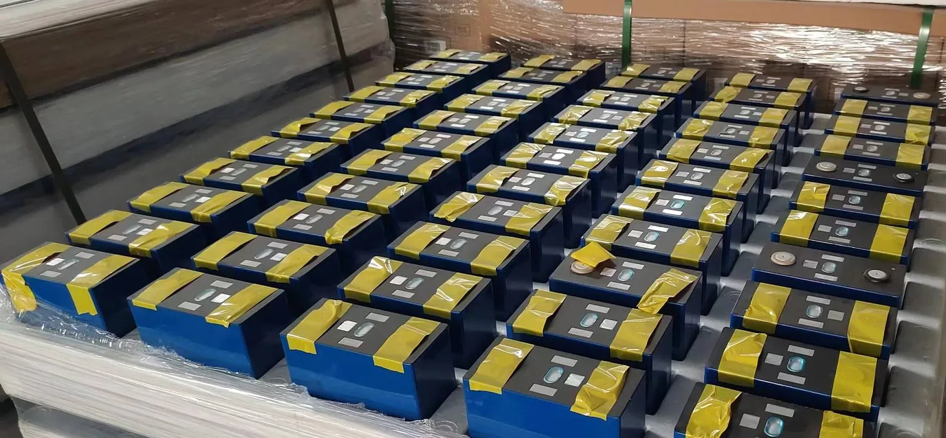
Every figure below comes from comparative bench runs under standard duty cycles — not from supplier datasheets.
Specification notice:The figures above are engineering reference values. They may differ with production batch, configuration and actual duty cycle, and the percentages for life, efficiency, availability and coverage are engineering estimates and bench references. Contact us for the detailed specification sheet.
The difference between a stationary ESS cell and a motive cell is not capacity. It is the systematic gap in C-rate, internal resistance, thermal path, vibration construction and the test regime behind the cycle-life claim.
Motive cells sustain 3.0C continuous and 5.0C transient overload for 15 seconds. ESS cells polarise violently above 0.8C and their protection board latches off.
Loaded 20° hill start: 160A~220A instantaneousCell DC internal resistance is ≤ 0.35 mΩ on motive cells versus ≥ 1.20–1.80 mΩ on ESS cells. At 3.4× the resistance, the same current produces 11.5× the Joule heat (P = I²R) and accelerates separator breakdown.
3.4× the resistance → 11.5× the heatMotive modules use ISO 12405-3 automotive laser-welded busbars and high-elasticity silicone retention. ESS modules are built for static rack mounting; simple threaded clamps shake loose on rough roads and short out.
50G three-axis shock · 100,000 rough-road simulation cycles passedAt 45°C ambient, motive cells rise ≤ 0.35°C per minute through an integrated stamped heat-conduction channel and an air-gap duct. ESS cells rise ≥ 1.60°C per minute, packing heat into a sealed stack that swells and leaks.
50°C chamber: motive 58℃ / ESS 82℃Under a loaded tuk-tuk or cargo tricycle pull-away, a motive pack absorbs 200A–250A with voltage held within 5% and no loss of drive. An ESS pack trips hard at 60A–80A, cutting power mid-gradient and rolling back.
Voltage sag at 150A step: 0.12V vs 0.58VThe 6,000-cycle claim on ESS cells comes from a 0.2C laboratory light-cycling regime. Motive cells are tested at 1.0C full charge and discharge to ≥ 3,500 cycles, which maps to five to seven years of intensive passenger operation.
ESS under vehicle current: under 600 cycles (about 9 months)Data source: a 180-day continuous comparative duty-cycle run across the same load profile.
| Parameter and test dimension | TIANQIU automotive motive LiFePO4 (EV-grade) | Typical retrofit stationary ESS cell |
|---|---|---|
| Discharge C-rate continuous and transient pulse | 3.0C continuous / 5.0C transient pulse (15s) instant torque on loaded acceleration and steep gradients | 0.2C–0.5C rated / 0.8C–1.0C peak pulse above 1.0C it overheats badly and the protection board latches |
| Cell DC internal resistance (IR) 100Ah format at 25°C | ≤ 0.35 mΩ (motive-grade matched sorting) ultrasonically thickened tab welds, minimal Joule heating | ≥ 1.20 mΩ ~ 1.80 mΩ (ordinary ESS grade) 3.4–5× the motive value; most energy becomes heat |
| Loaded start-up transient tolerance tuk-tuk / cargo tricycle pull-away under load | 200A–250A absorbed smoothly voltage held within 5%, drive never interrupted | 60A–80A causes hard voltage collapse and tripping the meter alarms mid-gradient and the vehicle stalls, with roll-back risk |
| Thermal construction and rate of rise tropical 45°C extreme duty | ≤ 0.35°C / min separate stamped conduction channel plus air-gap cooling duct | ≥ 1.60°C / min (sealed heat accumulation) densely packed with no gap; the core swells and leaks |
| On-vehicle shock and vibration grade unpaved roads, potholes and washboard | ISO 12405-3 / 50G three-axis shock certified fully laser-welded busbars, high-elasticity silicone retention | Static rack mounting only (no vibration reinforcement) simple threaded clamps loosen within 3 months and arc |
| Real cycle-life basis 80% capacity retention end point | ≥ 3,500 cycles at 1.0C full charge/discharge equal to 5–7 years of intensive passenger duty | Claimed 6,000 cycles (0.2C laboratory light cycling) fewer than 600 cycles under vehicle current (about 9 months) |
| Tab and busbar current cross-section physical current-carrying limit | Multi-tab wide copper busbars (45mm² cross-section) low temperature rise, minimal current-collector voltage drop | Single narrow tab (15mm² cross-section only) the tab fuses or the insulation film burns through under high current |
Seven directly reproducible dimensions are shown above; the full ten-parameter dataset and raw curve reports are available per project.
Specification notice:The figures above are engineering reference values. They may differ with production batch, configuration and actual duty cycle, and the percentages for life, efficiency, availability and coverage are engineering estimates and bench references. Contact us for the detailed specification sheet.
Without a laboratory, how do overseas distributors and fleet technical managers identify a cheap ESS cell passed off as a motive pack — using only the physical unit and portable tools?
Every genuine motive cell carries a 24-character laser-engraved code on the steel can. Query the factory database and read the prefix: motive (EV/Power) and stationary (ESS/Solar) grades occupy strictly separate code ranges. Any code that has been ground back, sandblasted or re-labelled with a new sticker is 100% a refurbished ESS or downgraded cell.
Anti-counterfeit check: no grinding or sandblasted pitsWith a multimeter or the BMS Bluetooth app, blip the throttle for two seconds with the vehicle fully loaded or the rear wheel locked (about 100A instantaneous). If a cell falls from 3.32V to below 2.90V — more than 0.4V of sag — the internal resistance is too high and the cell is definitively a low-rate ESS unit. A genuine motive cell typically sags less than 0.15V.
Benchmark: ΔV < 0.15V indicates a good motive cellOpen the lid and sample a cell: motive cells use fully laser-welded extra-wide pure copper busbars (thickness ≥ 2.0mm), with a substantial current cross-section and no thread oxidation. If you find thin stamped nickel strip (thickness < 0.5mm) fixed with screws, that is a standard static ESS assembly and must never be used on a vehicle.
Hard line: thick copper, laser-welded, no exceptionsA compliant export traction battery must state two figures on the nameplate: rated continuous current (Continuous Amps) and peak overload current (Peak Amps @10s), together with its UN38.3 reference. ESS packaging tends to say only "capacity 100Ah" and avoids the maximum continuous current entirely.
Nameplate must show continuous and 10-second peak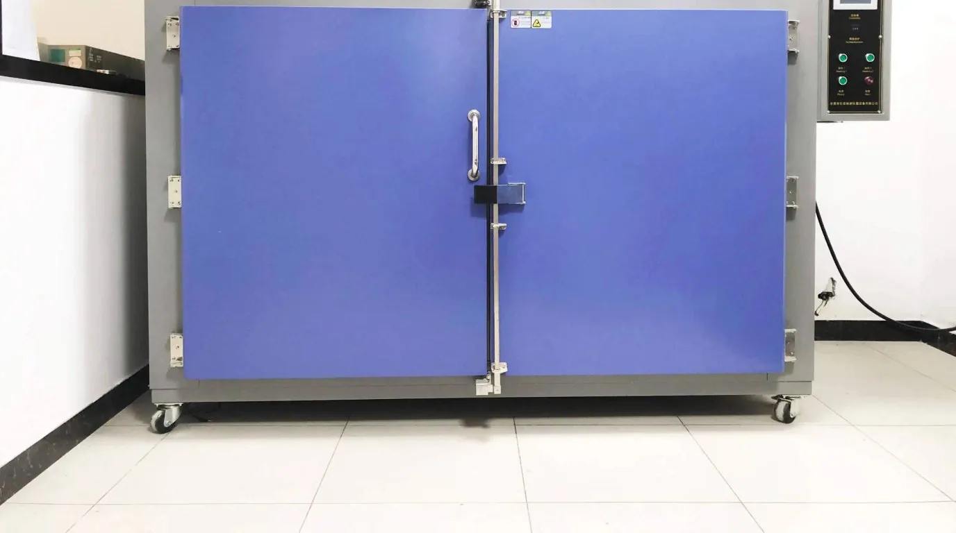
On flat ground at low speed, an ESS pack can still limp along on shallow cycling. But in peak-hour shared rides (four passengers plus a driver) or carrying 500kg of agricultural produce, the motor is held in reverse-torque for sustained 2.5C–3.0C output for up to 30 seconds. At that point ESS polarisation voltage consumes 25% of the pack's usable power output, with heat generation above 800% of a motive cell.
The conclusion from 180 continuous days on the same bench is blunt: what gets underestimated is never capacity, it is voltage hold under transient high current. The TIANQIU industrial laser-marked heavy-duty motive pack uses a one-piece stamped steel shell, an external Anderson reverse-polarity-proof high-current connector, an independent pressure-relief valve and thermal isolation pads — stable through 50°C African heat and high-humidity salt spray.
Many assemblers treat a $150 lower price per ESS pack as a cost advantage. In operation, the losses from fast thermal fade and frequent mid-route cut-outs dwarf that purchase gap.
These are not theoretical risks; they are the failure modes fleets report after fitting stationary ESS cells.
An ESS BMS limits current to about 80A while a loaded three-wheeler pull-away demands 160A. Cell voltage is forced into the cut-off region, drive is cut without warning, and roll-back into traffic follows.
High ESS internal resistance under a tricycle floorpan with no cooling path boils the electrolyte. Visible swelling and leakage typically appear within 6-8 months.
Static threaded connections work loose after about 2,000km of unpaved road, contact resistance rises geometrically, and a harness ignites under high-current discharge.
A single narrow tab with only 15mm² of cross-section runs beyond its physical limit under vehicle current, fusing the tab or burning through the insulation film — a direct route to internal short circuit.
Dismantling misleading claims from cheap cell suppliers, and setting the baseline for export powertrain specification.
Avoid tens of thousands of dollars in trial-and-error cost. Send your fleet requirement and our engineering team will reply within 24 hours on working days with the complete analysis of temperature rise, charge/discharge rate curves and cell impedance dispersion across the 48V/60V/72V three-wheeler range, plus the option to book a bench sample pack.
Specification notice:The figures above are engineering reference values. They may differ with production batch, configuration and actual duty cycle, and the percentages for life, efficiency, availability and coverage are engineering estimates and bench references. Contact us for the detailed specification sheet.
Vehicle duty cycles and technical requirements you submit are used only for this specification study and remain strictly confidential.